Understanding the difference between PONA and PIONA

Understanding the difference between PONA and PIONA

Guided Wave News / By 

Near-infrared (NIR) technology can overcome the major problems associated with real-time inline monitoring of process hydrocarbon streams. In the case of the Naptha Steam cracker and other olefin units in the Refinery, PIONA (Paraffins, Isoparaffins, Olefins, Napthenes, Aromatics) are important properties. Naphtha feed streams can in principle be measured on-line by GC techniques, but the parameter measurements required for effective control include PIONA and %Distillation curve, which require long elution times and the added cost of a sample conditioning system.

PIONA Petrochemcial (Hydrocarbon) molecules measured by NIR Spectroscopy.

PONA vs PIONA, what’s the difference?

PIONA is a more exact measurement standard. PIONA considers n-paraffins and isoparaffins to be different.  N-paraffins have long straight chains and provide higher cetane values for diesel fuels. The melting point of n-paraffins often occurs between 230-370°C, which results in a worsening of the cold flow properties (cold filter plugging point, pour point) of the diesel fuel. Isoparaffin molecules, such as iso-butane, contain branched side chains. As a result, isoparaffins increase the viscosity, lower pour point, and increase the octane of the fuel. The ratio of n-paraffins to iso-paraffins is an important parameter in some fuel blending operations.

Questions? We’re here to help.

Contact Us

Continue reading

Utilizing the Direct-Digital MODBUS interface for ClearView db – OEM Applications

Utilizing the Direct-Digital MODBUS interface for ClearView db – OEM Applications

ClearView db is a modular filter photometer suitable for many OEM applications. By selecting up to six filters ranging from 420nm to 2100nm each with a dedicated detector, system integrators have successfully utilized ClearView db for real-time monitoring of liquids and gasses. Examples include: acid & OH number monitoring, detection of copper in acid baths, hydrogen peroxide vapor sterilization, NO2 gas sterilization, water content of solvent or gasses, or color. Additionally, the ClearView db can monitor up to 2 process locations using either flow cells or direct insertion probes.

Guided Wave provides OEM partners with a detailed MODBUS TCP/IP map and implementation examples. This data enables system integrators to quickly incorporate the ClearView db into their existing projects. MODBUS enables directional communication and remote operational control of the analyzer. Commands include: taking a reference, zero, or background scan; applying a slope and bias correction to the measurement result; and alarms or errors. For example, analyzer faults or off spec process alarms. ClearView db monitor does not require an external computer for configuration and operations, Modbus TCP/IP communication is completely integrated into the system and does not need extra software or hardware from a third party supplier

Ultimately by implementing the OEM ClearView db photometer with MODBUS, critical process monitoring information can be quickly delivered to process engineers and other end-users. Allowing your customers to make informed decisions in real-time.

Interested in learning more about the OEM process for the ClearView db?

Understanding MODBUS Bit Fields in the ClearView db

The ClearView db does not implement MODBUS bit commands such as Read Coils, Write Coils or Read Input bits. To reduce computational time, the ClearView db instead employs the use of bit fields in unsigned 16 bit words. The table below displays a partial MODUS map for the ClearView db. A complete MODBUS map is provided to OEM partners.

ClearView db Modbus Address 40003 Read / Write Example

BitNameDescription
0RunThe Run bit is set at power up and should be set at all times except during configuration changes. This bit is cleared when the touch screen configuration menu is accessed and set upon exit from the configuration menu screen. When Run is cleared the analyzer will no longer calculate Transmission, Absorbance, Answers or update Analog Output values.
1Referencing ASetting this bit will cause the analyzer to Reference / Zero Channel A. The bit will auto clear when completed. The Run bit must be set for this command to work properly.
2Referencing BSetting this bit will cause the analyzer to Reference / Zero Channel B. The bit will auto clear when completed. The Run bit must be set for this command to work properly.
3Configuration ActiveThis bit is set by the touch panel when the configuration menus are being accessed and cleared when the configuration screens are exited.
4Program SaveSetting this bit will cause the analyzer to save all of the answer configuration settings currently in RAM into EEProm. This bit will auto clear when completed. The Run bit should be cleared before setting this bit and then set after completion.
5Program LoadSetting this bit will cause the analyzer to load all of the answer configuration settings from EEProm into RAM. This bit will auto clear when completed. The Run bit should be cleared before setting this bit and then set after completion.
6Hardware Save
Factory Use Only
Setting this bit will cause the analyzer to save all of the Factory configuration settings currently in RAM into EEProm. This bit will auto clear when completed. The Run bit should be cleared before setting this bit and then set after completion. Factory settings apply only to installed components that cannot be changed in the field.
7 - 14Not used
15Analog Output TestSetting this bit cause the analyzer to enter Analog Outputs Test mode. This test cycles the 4-20mA outputs continuously 4ma, 12mA and 20mA for several seconds each until cleared.

Questions? We’re here to help.

Contact Us

Continue reading

Vaporized Hydrogen Peroxide – Applications and Monitoring Solutions

Vaporized Hydrogen Peroxide – Applications and Monitoring Solutions

Sterilizing medical instruments in autoclave

Questions? We’re here to help.

Contact Us

Continue reading

What are you Measuring? When to know if Process Spectroscopy is the Measurement Technology you should use.

When to know if Process Spectroscopy is the  Technology you need for Liquid, Vapor or Gas Measurements?

Use this flowchart to figure out if process spectroscopy is the best measurement technology for your application.  If you reach the purble box (I don’t know) in this flowchart you can complete the Application Questionnaire and the experts at Guided Wave will help you. There is also more information on the how to select an analyzer page. Want to send us a question? Use the contact us button below.

When to Know if Process Spectroscopy is the Technology for Liquid, Gas or Vapor Measurements

Which Process Spectroscopy Analyzer did you Choose?

Select the product name below for more information about each of these Guided Wave and ANALECT analyzers: 

Flowchart

QUESTIONS? WE’RE HERE TO HELP.

contact us

Continue reading

Canadian Registration Number (CRN) Certified Probes for Process Spectroscopy

Canadian Registration Number (CRN) Certified Probes for Process Spectroscopy

A Canadian Registration Number (CRN) is a number issued to the design of a pressure vessel or fitting by each province or territory of Canada. The CRN identifies the design has been accepted and registered for safe installation and use. As of October 2019, Guided Wave has submitted more than 3,500 different design configurations for our probes and flow cells to be CRN certified.

CRN certified probes and flow cells are engineered by Guided Wave to meet the strict safety and application requirements for the Canadian petrochemical, refining, and polymer markets. By coupling these probes with certified (CSA, ATEX, IECEX) process analyzers, Guided Wave can offer complete process monitoring solutions to Canadian customers. We currently have CRN registered designs for Ontario, Alberta, and Quebec. However, complete process monitoring solutions for all provinces can be implemented – contact us for more information.

All CRN probe sales include hydrotest and x-ray test results.

Gold Braze Single-Sided Transmission Probe and Gear Driven Extractor

NIR-Infrared spectroscopy with both DG-NIR and FT-NIR is now possible with the family of CRN certified in situ transmission probe and extractor.

CRN Probe Features

  • Corrosion resistant construction
  • Rugged and vibration resistant design
  • Sealed against ambient moisture infiltration
  • High optical throughput for low noise spectroscopy
  • Temperatures to 300 °C
  • Pressures to 2000 psi or 138 bar
  • Higher pressures are available on request

Optional CRN Certified Accessories

The Single-Sided Transmission probe is available with an Extractor Assembly under a single CRN. This extractor accessory allows for a CRN probe to be easily adapted to different kinds of process installations. Additionally, the Extractor Assembly allows for quick and easy removal and servicing of probes, and avoids costly shutdowns by allowing the process to continue while the probe is offline. The standard flange on the extractor enables it to be installed into common process pipe configurations.

Certified Probes for High Pressure and Temperature Applications

The family of Heavy Duty probes are a special class of SST probes designed to withstand up to 2400 psi. The Heavy Duty probes can be constructed in 304, 304L, 316, 316L, and Hastelloy, with up to a 50 mm path length. 

CRN Certified Flow Cells for NIR Spectroscopy

Guided Wave’s family of 1, 2, 5, 10, and 20 mm pathlength flow cells are hydro-tested to demonstrate operation at 8100 pounds of pressure. This high safety factor has enabled Guided Wave to seek CRN certification for the flow cells in Ontario, Alberta, and Quebec.

Simple, Serviceable Flow Cell Design

Key elements of the CRN Certified flow cell (MPFC) design are simple, serviceable o-ring seals, the clean-out port, high optical efficiency, slip jointed conduit-ready connections, sapphire windows, a clean flow pattern, and o-ring sealed optics to prevent ambient moisture infiltration. The flow cell probe can be field disassembled for o-ring service and reassembled without changing the optical pathlength, a crucial parameter for repeatable measurements. The multi-purpose flow cell now boasts a dual seal at the sapphire “window-to-process” interface. This doubles protection for the expensive internal optical lenses.

Operating Range of CRN Flow Cell

The certified Multi-Purpose Flow Cell operates over the following pressure and temperature ranges:

  • Temperatures to 300 °C (o-ring material dependent)
  • Pressures to 1000 psi (o-ring durometer dependent)
  • Available in five standard pathlengths 1, 2, 5, 10, and 20 mm

CRN Certified Probes Compatible with Bruker and ABB Spectrometers

The CRN Certified probes and flow cells are manufactured by Guided Wave to facilitate full integration with any fiber-optic spectrometer manufacturer. The family of CRN certified devices are fully compatible with the Matrix-F FT-NIR analyzer, ABB’s full line of FT-NIR spectrometers, and AIT’s optical analyzers. The market-leading optical efficiency of our sample interfaces will improve the optical performance any spectrometer when connected with 400 to 600 micron fiber optical cables and SMA 905 or FC connectors.

Need Help Purchasing a CRN Certified Spectroscopy Probe or Flow cell?

Contact a Guided Wave sales representative to determine the best CRN Certified configuration for a process sample interface.

QUESTIONS? WE’RE HERE TO HELP.

contact us

Continue reading

Announcing direct integration of EigenVector’s SOLO Predictor with Omniview V2.0 software

Announcing direct integration of EigenVector’s SOLO Predictor with Omniview V2.0 software

Eigenvector Research and Guided Wave have partnered to implement an API between the Omniview V2.0 software and Solo_Predictor. This enables NIR-O Full Spectrum Analyzer users who develop models using Eigenvector’s MATLAB® based PLS_Toolbox or stand-alone Solo to use the real-time prediction engine, Solo_Predictor. Contact Guided Wave or your local representative to access this free of charge software update.

Steps to for Existing NIR-O Users to Implement Solo_Predictor

Time needed: 15 minutes.

Steps to integrate Solo_Predictor and Omniview Software.

  1. Provide proof of runtime license for the Solo_Predictor program
  2. Download software update from Guided Wave onto built-in analyzer PC

    A zip file containing updated python scripts and a 64-bit Solo_Predictor version 4.0.4 installation executable will be provided by sharepoint or drop box.

  3. Follow the installation procedure

    The installation procedure for existing users, requires moving some files into place.

Purchasing a NIR-O and want SOLO_Predictor to be preinstalled?

Existing EigenVector customers just need to provide proof of the run-time license when placing their order with Guided Wave. This will allow our production staff to implement the API on the analyzer computer.

QUESTIONS? WE’RE HERE TO HELP.

contact us

Continue reading

What’s a Photometer filter kit and how can it help me save money?

What’s a Photometer filter kit and how can it help me save money?

Solid state filters are used in the ClearView db analyzer. The apparent color change represents different wavelength ranges. These filter are installed inside of the filter wheel in the ClearView db Analyzer

The ClearView db process analyzer is a photometer-based sensor platform. Before shipment, each platform is configured in Guided Wave’s factory to monitor specific conditions or applications specified by the end-user. The Clearview db provides a cost savings alternative to purchasing a process grade spectrometer. The cost savings are achieved by selecting (at the time of purchase) up to six filters, which are part of the analyzer’s hardware.

Each filter is chosen based upon the compounds to be measured. Every filter allows a ~10nm wide wavelength band of the analyzer light to reach the detector. All other light is essentially blocked by the filter. These filters are then installed inside the ClearView db, locking in the hardware portion of the calibration (The wavelengths that are measured). The software calibration is typically done in Microsoft Excel by the factory and converts the intensity of light for each filter/wavelength into the predicted answer.

The ClearView db delivered to the end-user is essentially customized for their specific purpose. The end-user may later modify the software portion of the calibration to adapt the analyzer for other requirements. For example, an offset or slope correction can be added to fine-tune the calibration based on data after installation at the customer site.

How Guided Wave Selects Filters?

Guided Wave has developed filter kits for many applications. For new applications, samples must be collected and scanned with a spectrometer (400-2100nm). Wavelength ranges that correlate well with the chemical changes are identified and compared against our stock of available filers for the closest match.

Each filter allows a narrow range of wavelength to be transmitted to the photometer detector. This is typically referred to as the bandwidth of the filter. Above are 4 proven photometer applications by wavelength represented by the red, gray, blue and yellow dots. By measuring these wavelengths we can monitor the specific application at a reduced cost in comparison to a full spectrum analyzer.  

If Guided Wave does not have a corresponding filter, a custom filter can be ordered from our vendor and added to our inventory to meet application demands.

The Anatomy of the ClearView db Analyzer

The photometer both transmits the source light and quantifies the light that was not absorbed by the sample. Optical grade fiber cablesare used to carry the light from the photometer to the sample and back. Using high-performance fiber cables permits the sample interface to be located up to 100 meters from the photometer.

The ClearView db can be divided into four major sections 

1) Electronics (Detector PCA):  the desired (analog inputs and outputs, Modbus interface, and Human Interface Display (touch screen)

2) Lamp Housing:  area of the light source.

3) Optical Multiplexor: (MUX): which programmatically switches between the reference and sample fiber optic cables. The reference fiber is our Dual Beam (db). It allows for automated corrections due to instrument noise and improves performance.

4) Detector Housing:  area where the filters and detectors are installed by Guided Wave at the factory (the graphic below shows 2 of the 6 possible filters).

ClearView db Photometer -Filter

Questions? We’re here to help.

Contact Us

Continue reading

Alphabet Soup or Calibration Acronyms PART II

Alphabet Soup or Calibration Acronyms PART II

As the field of process spectroscopy grows, so does the number of acronyms associated with the measurement methods. In the last blog post, we discussed the acronyms related to calibration that users may encounter. This blog will give a brief overview of some acronyms that are in frequent use related to Guided Wave analyzers and products. Some of these are specific to Guided Wave, while others are related to the methodology as a whole. The list below is in alphabetical order.

ANSI – American National Standards Institute
The ANSI is a private nonprofit organization that oversees the development of voluntary consensus standards for products, services, processes, systems, and personnel in the United States. The organization also coordinates U.S. standards with international standards so that American products can be used worldwide. These standards ensure that the characteristics and performance of products are consistent, that people use the same definitions and terms, and that products are tested the same way.

ASTM – American Society for Testing and Materials
ASTM International is one of the largest voluntary standards development organizations in the world. They are a source for technical standards for materials, products, systems, and services. ASTM International standards have an important role in the information infrastructure that guides design, manufacturing and trade in the global economy.

ATEX
The European directive 94/9/EC requires that employers must protect employees from explosion risk in areas with explosive atmospheres. Manufacturers and importers must ensure that their products meet specific safety requirements. The goal of ATEX, which gets its name from the directive’s French title Appareils destinés á être utilisés en ATmosphères Explosibles, is to allow free trade of “ATEX” approved equipment within the EU by removing the need for separate testing and documentation for each member state.

CENELEC
CENELEC is the European Committee for Electrotechnical Standardization. This is a non-profit technical organization set up under Belgian law and composed of the National Electrotechnical Committees of 30 European countries. CENELEC’s mission is to prepare voluntary electrotechnical standards that help develop the Single European Market/European Economic Area for electrical and electronic goods and services removing barriers to trade, creating new markets and cutting compliance costs.

FT-NIR
Fourier transform spectroscopy is a measurement technique whereby spectra are collected based on time-domain measurements of the electromagnetic radiation. It can be applied to a variety of types of spectroscopy, including Near-Infrared spectroscopy (see NIR below).

ISO
ISO is an international-standard-setting body composed of representatives from various national standards organizations. The organization promulgates world-wide proprietary industrial and commercial standards. ISO is a network of the national standards institutes of 157 countries, one member per country, with a Central Secretariat in Geneva, Switzerland, that coordinates the system.

NIR
Near-Infrared or NIR is a region of the electromagnetic spectrum from about 750nm to 2600nm. Near Infrared Spectroscopy is the technique of using a sample’s NIR absorbance characteristics to predict parameters of interest. Molecules containing C-H, O-H, and N-H bonds absorb NIR radiation in specific regions or at specific wavelengths. These absorbance’s can then be used in a qualitative or quantitative measurement. NIR spectroscopy is widely used in both process and laboratory measurements across many industries (chemical, refining, pharmaceutical, polymer, semi- conductor, agricultural).

NIST
The National Institute of Standards and Technology (NIST), previously known as the National Bureau of Standards (NBS), is a non-regulatory agency of the United States Department of Commerce. The institute’s mission is to promote U.S. innovation and industrial competitiveness by advancing measurement science, standards, and technology in ways that enhance economic security and improve quality of life.

PAT
Process Analytical Technology (PAT) has been defined by the United States Food and Drug Administration (FDA) as a mechanism to design, analyze, and control pharmaceutical manufacturing processes through the measurement of critical process parameters and quality attributes. While this term was initially defined in relation to the pharmaceutical industry, the concepts and methods can be extended to other industries.

SST
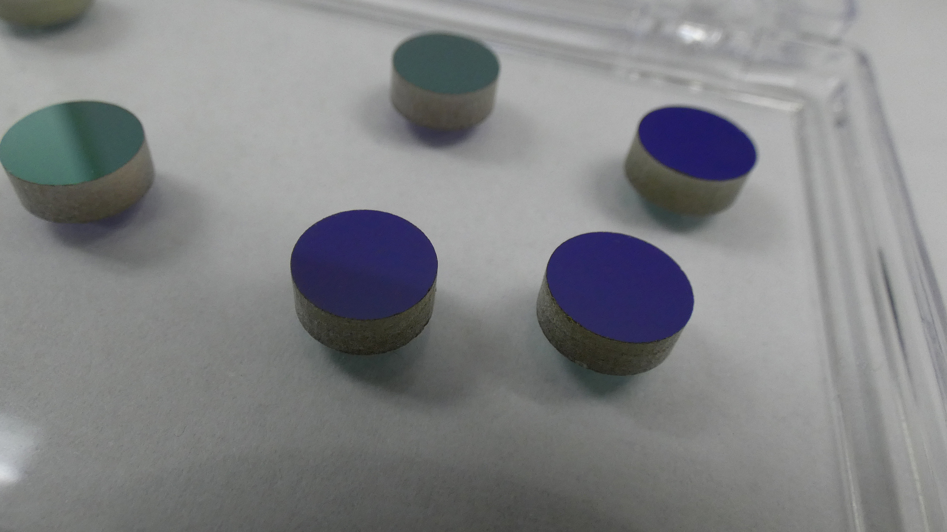
The Single-Sided Transmission (SST) Probe is a rugged and reliable sample probe that is ideal for continuous process monitoring applications. SST means that light passes through the sample region only once. In contrast, transflectance probes pass twice, being reflected from the far end. The SST probe can be easily installed in a pipe or reactor through a single access port and works with any Guided Wave single-fiber spectrometer or photometer. Optional accessories make it easy to adapt the SST Probe to different kinds of process installations.

UV/VIS
UV/VIS spectroscopy is the measurement of the wavelength and intensity of absorption of ultraviolet and visible light by a sample. Ultraviolet and visible light are energetic enough to promote outer electrons to higher energy levels. UV/VIS spectroscopy is usually applied to molecules and inorganic ions or complexes in solution. The spectra have broad features that are of limited use for sample identification but are very useful for quantitative measurements. The concentration of an analyte in solution can be determined by measuring the absorbance at some wavelength and applying the Beer-Lambert Law.

Calibration Acronyms

ANSI- American National Standards Institute
ASTM- American Society for Testing and Materials
ATEX- Atmosphéres Explosibles (French)
CENELEC- European Committee for Electrotechnical Standardization
CIE – International Commission on Illumination
FT- NIR- Fourier Transform Near-infrared
ISO- International Organization for Standardization
NIR – Near-Infrared
NIST- National Institute of Standards and Technology
PAT- Process Analytical Technology
SST- Single Sided Transmission Probe
UV/VIS- Ultraviolet / Visible

QUESTIONS? WE’RE HERE TO HELP.

contact us

Continue reading

35 Year Anniversary!

35 Year Anniversary!

From 1983 to 2018 – Guided Wave a leading manufacturer of online process analytical systems is pleased to announce the 35th anniversary of continuous business operation. Established in 1983, Guided Wave was an industry pioneer when it delivered the first fiber optic-based Near Infrared (NIR) analyzers. Read our story of 35 years

Questions? We’re here to help.

Contact us

Continue reading

Writing Custom Python Scripts in OmniView Part II

Writing Custom Python Scripts in OmniView Part II

Writing Custom Python Scripts in OmniView Part II

In part I of Writing Custom Python Scripts in OmniView, we discussed setting up a basic python script and determine the absorbance value at a specific wavelength. As shown in our training videos we recommend customers use Unscrambler Prediction Engine to implement PLSR or PCA calibrations. We also have a video demonstrating how to turn on additional statistics, such as Mahalanobis Distance.

When additional statistics are turned on, instead of returning a single floating point value, the Unscrambler Prediction Engine will return a python dictionary or array of answers (predicted properties). If you are operating near zero, the calibration may return a negative result. In many applications the answer, such as the concentration of water in a solvent, the real world value can never be less than zero. Therefore you may want to add some logic to your python method script to overwrite negative values and set them to zero.

The code below can be added to your custom python method script. Please note the tab indentation. Proper spacing is important in python syntax.

answer = unscramble(au)

for key in answer.keys():
    if answer[key] < 0:
        answer[key] = 0

Interested in learning more? Check out the training videos we have on our youtube channel.

Questions? We’re here to help.

Contact Us

Continue reading