How to Select the Best Fiber Optic Cable for High Performance Spectroscopic Analysis
Knowing how to correctly select, install and maintain the fiber cabling is important to optimizing the system and thus the results. Inline, flexible, fiber optic process analyzer systems enable users to place measurement probes remotely and at multiple points with one instrument, dramatically reducing cost. Additionally, optically matching fiber to the spectroscopic analyzer will achieve optimal system performance results.
5 Questions to Consider When Selecting Process Grade Fiber Cable:
- Optical wavelength range of use
- Diameter of the optical fiber cable
- Environmental conditions
- Required distance for signal transmission
- Installation requirements

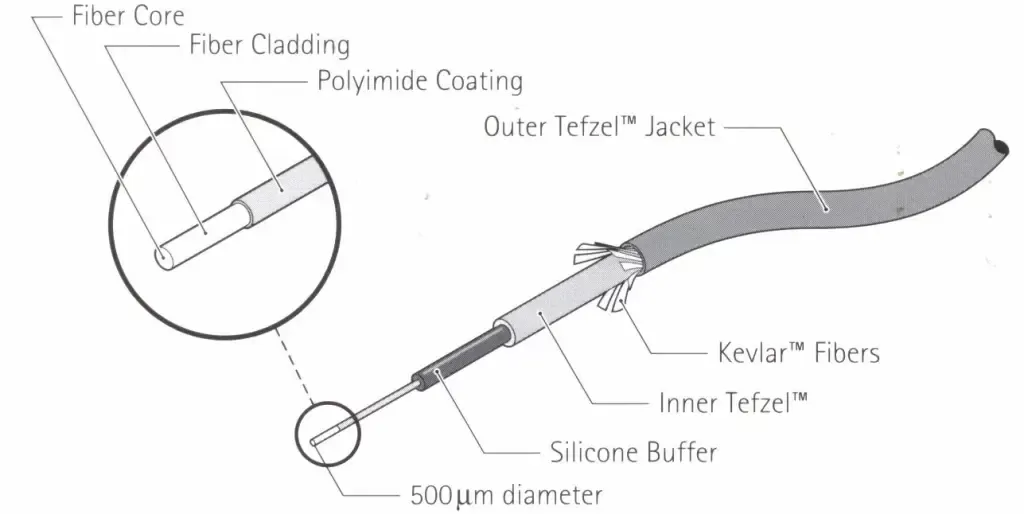
Anatomy of A Guided Wave Fiber Optic Cable
1) Optical Wavelength Range of Use
There is much confusion regarding the use of telecommunication fibers versus spectroscopic grade fibers. Telecom typically uses monochromatic pulsed light from either an LED or laser. They only need to detect whether the light is on or off at the end of the fiber. Typically, telecom fiber is small diameter since smaller diameters carry the light more efficiently and are cheaper. Spectroscopy uses polychromatic light and must measure the amount of light at the end of the fiber to one part in one million. Obviously, the latter is a much more difficult measurement. As a result, it is necessary for the spectroscopic fiber usually to be much larger in diameter.
Fiber optic cables work by total internal reflection of the light. The core of the fiber is typically high purity fused silica surrounded by a higher index of refraction doped fused silica cladding layer. The carrying capacity of the fiber is determined by the product of the core cross-sectional area and the acceptance cone angle (numerical aperture) of the fiber.
Spectroscopic grade fibers are optimized for the wavelengths of use. For UV (190 nm to 550 nm) applications, high hydroxyl group (OH) fused silica is used. It must be treated to prevent solarization (darkening caused by UV damage) of the fiber. For near infrared (NIR) (800 nm to 2200 nm) applications, low OH fused silica is the optimal material. Low OH fiber is required because the OH radical has a NIR spectrum that would interfere with the spectral measurements. For visible (380 nm to 700 nm) applications, either fiber will work.
2) Diameter of the Optical Fiber Cable
Optical fiber comes in a wide range of core diameters, from single mode fiber, about 6 µm in diameter, to multimode fiber up to 1000 µm in diameter. The core diameter along with the numerical aperture determines the light carrying capacity. Light is lost at every fiber interface, by reflection losses, misalignment or mismatches of the fiber diameter and other optical interfaces. The objective in fiber optic instrument design is to minimize the number of interfaces and maximize the optical matching at these interfaces.
Larger core fiber is more expensive (more glass volume per unit length), less flexible and has a higher attenuation rate with distance. For short hauls it does carry more light, therefore, can yield a better signal-to-noise ratio. But installing larger core fiber may not capture more light if the instrument it is connected to does not take advantage of the larger diameter. Typically, most fibers used for spectroscopy are 200 µm, 400 µm, 500 µm or 600 µm core diameters.
Guided Wave started designing grating-based spectrometers over 35 years ago. In the process, the engineers learned that they could eliminate one of the slits of the spectrometer and replace it with the fiber if the correct fiber diameter was used to match the required bandwidth and f/No. of the spectrometer. This eliminated one source of optical loss. Thus, Guided Wave spectrometers were standardized on 500 µm diameter fiber with a numerical aperture of 0.22 (~30° cone angle). Consistently using 500 µm core diameter fiber throughout the analyzer system optimizes the performance of the instrument. The N.A. of 0.22 is roughly an f/2 cone of light the matches the f/No. of the spectrometer, so once again the throughput of the system is optimized.
500 µm core fiber has other advantages as well. It is cheaper and more flexible than 600 µm core fiber and has 56% more light carrying capacity than 400 µm fiber.
3) Environmental Conditions
Unprotected optical fiber is fragile, hence the fiber is typically installed in a jacket to protect it. There are many jacket types that can be used depending on the environmental conditions to which the cable is exposed. For benign laboratory conditions, PVC or metal mono coil jacketed cable works fine. The cable is flexible and easy to route. It has an upper temperature limit between 65°C and 100°C. Available lengths are short (<20 meters).
A more rugged cable construction is BX armored. This construction is used were the fiber is possibly exposed to physical damage. The BX may or may not be covered in PVC which again limits the upper temperature of the cable. BX fiber is limited to about 50 – 100 meters in length.
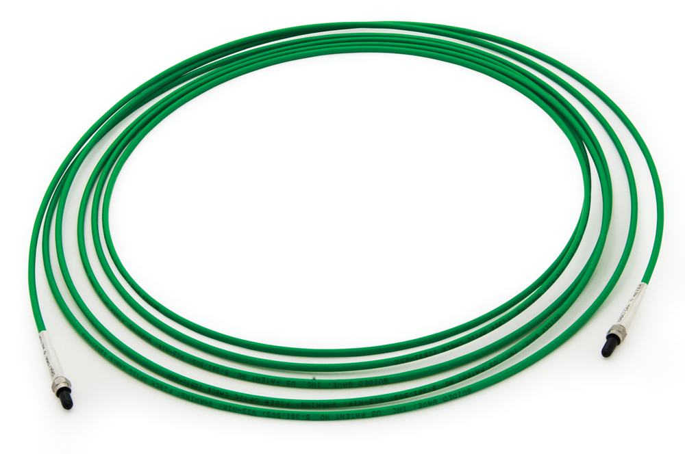
For longer industrial runs of cable, Guided Wave recommends Tefzel™ jacketed fiber. Tefzel is a Teflon™ like material that is strong, slick, and tough. This allows the cable to be pulled through conduit, laid in cable trays or to be exposed to the elements. It has an upper temperature limit of 165°C. Tefzel jacketed fiber is stiffer than the above options but this also helps prevent kinking and possible breakage. Since the jacket is applied to the fiber in an extrusion process, lengths are not limited.
Other environmental conditions may impact the performance of the fiber in a spectroscopic application. Strong sunlight can leak into the fiber thus introducing stray light into the measurement process which degrades the results of the analysis. Since this ambient stray light must penetrate the jacketing layer and the other protective layers on the fiber, it introduces spectral artifacts into the measurement. A good cable design prevents this infiltration of ambient light. For this reason, Guided Wave coats premium Tefzel jacketed fiber with a layer of carbon black impregnated RTV, room temperature vulcanized rubber, that is totally opaque to visible and NIR wavelengths.
4) Required Distances for Signal Transmission
When locating a process analyzer and probe, several things must be considered. The analyzer must be far enough away from the hazardous process to be safe, but close enough to make the fiber run practical from cost and performance points of view. Fiber cables are not cheap. The longer the run the more cost associated with the fiber especially if it is installed in protective conduit. Also, the amount of light available to the analyzer decreases with the fiber length due to internal absorption of the light and losses due to bends and other factors. Typically, it is preferred, for NIR applications, to keep the run length (one way) below 100 meters although lengths up to 300 meters have been accomplished.
The run length is also dependent on the spectral region to be used. UV cables must be kept short, typically under 30 meters due to the higher optical losses in the glass. Similarly, long wavelength use beyond 2000 nm requires shorter cable because the attenuation of the fiber increases strongly with wavelength in this region. Ask the experts at Guided Wave for assistance if there are any questions about the application and installation.
Guided Wave is frequently asked, “What is the maximum fiber length for the distance between the ClearView™ db Photometer and the sample?” Guided Wave’s high-performance fiber cables are typically used up to 100 meters (one way) for many NIR applications, although the actual allowable distance is dependent upon the exact measurements to be made and the process chemistry. The NIR-O™ full spectrum analyzer allows up to a few hundred meter of fiber cable. A distance of up to 300 meters is typically achievable for these NIR applications.
5) Installation Recommendations
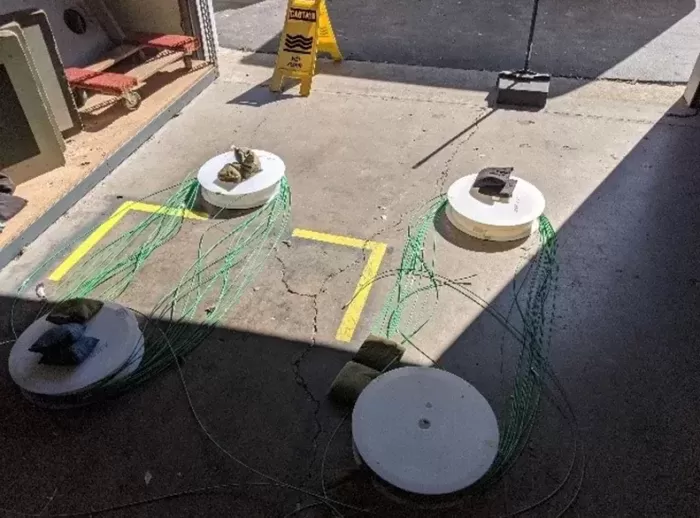
For the best performance, fiber optic cables must be installed properly. Sharp bends (<15 cm or 6” radius) must be avoided as this stresses the fiber and induces optical loss. Vibrations can add noise into the signal since they are a form of micro-bend losses. For industrial applications, conduit, either PVC or metal, is recommended to protect the investment and to prevent loss of critical analyses for the process. Finally, avoid routing fibers near hot process pipes since temperature does impact the transmission function of the fiber.
Fiber optic cables must be properly terminated. The most common termination used by most spectrometer and probe manufacturers are SMA connectors. For optimal use in spectroscopic applications, these connectors must be polished to perfection, be flat, square ended and the correct length. Otherwise there will be excessive losses at the connector, and it may introduce spectral artifacts such as fringes which will degrade the spectral measurement. For high temperature applications, the connector must be attached using high temperature epoxy.
Smart Considerations for Optical Fiber Cable Selection
For optimal system performance and savings, it’s important to properly select the optical fiber cables that will best match the spectroscopic analyzer system. Keep in mind the optical wavelength range, environmental installation conditions, required signal transmission distance, fiber diameter, and installation requirements. From a patented fiber design to an emphasis on high-quality materials, Guided Wave spectroscopic grade optic cable is designed for the highest performance in transmission efficiency and durability.
To help protect your investment follow the installation guidelines in the Fiber Optic Cable Instructions Technical Service Bulletin. For further questions call the experts at Guided Wave +1 916 638-4944.
Questions? We’re here to help.

Support: info@process-insights.com
TERMS AND CONDITIONS
TERMS AND CONDITIONS FOR SERVICE
SELLERS AGREEMENT
DATA PROTECTION
FRAUD ALERT
CHINESE
SITE MAP
-
Technology
Products
Blog
Applications
Application Questionnaire
ISO 9001 Certificates
Copyright © 2022 Process Insights, Inc. All Rights Reserved.


