• Home
  • Process Insights

Corporate Fellow Dr. Terry Todd Retires

Corporate Fellow Dr. Terry Todd Retires

Guided Wave recently announced the retirement of Corporate Fellow Dr. Terry Todd. Terry was celebrated with a farewell party at the end of 2019 where the entire staff thanked him for his over 27 years of dedication to the company. Susan Foulk, Guided Wave President, stated: “Terry’s vision, knowledge and leadership have been instrumental in our success and we sincerely thank him for all he has done and taught us throughout the years.”

With more than 40 years’ experience in infrared molecular spectroscopy and radiation physics, Terry specialized in optical and spectroscopic instrument design for industrial applications. At Guided Wave since 1992, he was responsible for developing new NIR and UV-VIS analyzer technology and applications. While at Guided Wave Terry was at the forefront of all new product development and introduction, from the introduction of the Hydrogen Peroxide Monitor in 1997 to the release of the NIR-O spectrometer in 2018.  During this time (1998) Terry also re-engineered the Single-Sided Transmission (SST) process insertion probe to improve the optical efficiency and further enhance its ruggedness and reliability. Elements of these improvements were awarded US Patent #6,043,895 (March 2000). This pursuit of continuous improvement demonstrates a fundamental aspect of Dr. Todd business practices. To this day, the SST remains one of the most copied, reliable, rugged, and efficient process insertion probes available and is still producing robust sales after more than 28 years in the marketplace. Author of several technical publications and conference presentations, Terry also taught NIR spectroscopy to Guided Wave customers and sales representatives.

Terry received a BS in Mathematics from Northern Illinois University in 1969. He followed that with an MS in Physics from Penn State University in 1972 with his thesis on the emission spectrum of CO2. In 1976 he was awarded his Ph.D. in physics also at Penn State. His emphasis was on molecular physics, infrared high-resolution spectroscopy and optics. His thesis was titled, “Spectrometer Design, Emission Spectrum of CO2 and Secondary Wavelength Standards”.

Between finishing his Ph.D. and joining Guided Wave in 1992 Dr. Todd held and completed the following positions and accomplishments:

  • 1976-1978   NBS-NRC Post Doc National Bureau of Standards, Gaithersburg, MD
    • 1st IR Spectrum of CS
    • Constructed Diode Laser Spectrometer
  • 1978-1980   Laser Analytics (Spectra Physics), Lexington, MA
    • Diode Laser Spectroscopy/Instrument Development
  • 1980-1991   Exxon R&E Co., Florham Park, NJ
    • Instrument Development
    • Laser Pyrometer
    • NIR Octane Monitoring
  • 1991-1992  Todd Enterprises, Inc., Budd Lake, NJ

Terry plans to spend his retirement enjoying more time with family and pursuing his many hobbies, one of which will be working on the restoration of his Opel sedans and coupes. He also plans to continue with liquids processing (winemaking, maple syrup, and apple cider). Please join us in congratulating Dr. Terry Todd on his illustrious career and newfound retirement!

Curtis Mau was promoted from Sr. Product Development Engineer to the role of Manager of Engineering / R&D and will fulfill many of Dr. Todd’s previous responsibilities.

QUESTIONS? WE’RE HERE TO HELP.

contact us

Continue reading

Advantages of Redesigned G-SST Probe for use with Hydrogen Peroxide (HPV) and Water Analyzer or other Low-Pressure Gas Applications

Advantages of Redesigned G-SST Probe for use with Hydrogen Peroxide (HPV) and Water Analyzer or other Low-Pressure Gas Applications

Guided Wave has been measuring H2O2 and H2O concentrations in various vapor mixtures for over 25 years using near-infrared (NIR), fiber optic-coupled analyzers. Guided Wave’s HPV analyzer is a simple turnkey solution for the measurement of hydrogen peroxide and water (H2O2 and H2O) concentrations in vapor phase. These are both measured together because they are codependent. The analyzer operates in real time, which takes the guesswork out of determining the H2O2 and H2O concentrations during cycle development and throughout the actual sterilization cycle. 

The complete system consists of an HPV analyzer, one or two G-SST probes, and a pair of fiber optic cables for each probe.

The first generation probe developed for measuring hydrogen peroxide in sterilizers was a single pass 25 cm probe.  Later this probe was vented for vacuum use yielding a path length of 28..3 cm.  This original design, exposed optics the optics (lenses) to the gases being measured.  Since lenses are sensitive to the index of refraction of the surrounding air which is a function of its constituency, in this case varying water and hydrogen peroxide vapor, this resulted in a small but detectable change in the effective focal lengths of the lenses.  As a result, baseline shifts could occur, which would decrease the accuracy of the absorption measurements and ultimately causes a small bias in the reported concentration of vaporized hydrogen peroxide during sterilization.

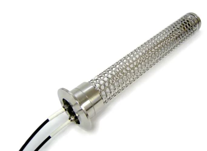
In 2003, GWI developed the first G-SST vapor probe, a double pass design with a pathlength of 50 cm.  The longer pathlength increased the accuracy of the measurement.  This probe still exposed the process side of the lenses to the sterilization chamber.  Once again, small changes in baseline could be seen as the air pressure and vapor concentrations changed.  Furthermore, the lenses were glued into place and after a couple of years of heavy service, the glue degraded due to exposure to hydrogen peroxide, necessitating service.  Below is a photograph of the original G-SST probe with its perforated tube design.

G-SST original double pass 50 cm probe with sanitary flange

Figure 1:  Original Double Pass 50 cm G-SST Probe with Sanitary Flange

In 2018, the engineering team at Guided Wave began a redesign project with the intention of reducing cost and improving the performance and service life of the G-SST probe.  GWI retained the 50 cm folded pathlength, the gold-coated second surface mirror and the high optical efficiency.  An o-ring sealed window was added to isolate the optics from the process. 

Primary Advantages New 50 cm Pathlength G-SST Over The Previous 25 cm, 28.3 cm and the Original 50 cm G-SST probe

  1. The double pass beam design (folded path) provides double of the beam interaction with the gases in the sterilizer chamber. This increases the achievable signal-to-noise making for a more accurate and stabile measurement. Since the absorbance of water and Hydrogen Peroxide vapor is very weak, this is a significant improvement in the measurement accuracy.
  2. The optics are sealed behind a window which isolates the lenses from the sterilization chamber; thus the probe is no longer sensitive to index of refraction changes, this makes the measurements are more stable under widely varying conditions of deep vacuum to high concentrations of water and hydrogen peroxide vapor.
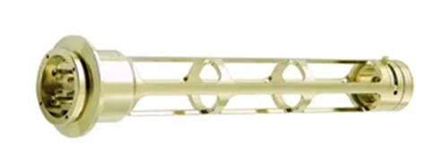
  3. To allow the probe to be quickly serviced by a technician, the perforated cage around the beam path was to the open structure shown in Figure 2. With the lenses behind an o-ring sealed window, there is no adhesive degradation increasing the service life of the probe.

In addition to these engineering improvements, the newly designed G-SST probe is a form, fit, and function replacement for the older style G-SST probes. This allows for nearly effortless upgrading for existing customers who purchase the new and improved style of G-SST. The G-SST vapor probe is available with either a tri-clover sanitary flange for mounting on a chamber access port or without a flange for placement within the chamber. By inserting the probe into the sterilizer through a 2” [50 mm] flanged port allows the fiber optic cables remain outside of the chamber and reduces measurement noise. Also, both the flanged and flangeless versions of the G-SST vapor probe can be 100% immersed in the sterilizer chamber with the addition of 2 small o-rings and a dual fiber feedthrough.

Improved Signal to Noise Through Folded Path Optics

The original 25 and 28.3 cm path length probes utilized single pass optics. As part of the redesign, a folded mirror configuration was developed, so that the light passes through the probe twice without significantly increasing the footprint of the probe. This design also keeps the optical fiber connections on one end and, when installed through a flanged port, outside of the process. To intentionally avoid measuring scattered light, the two paths are separated. By increasing the effective path length to 50 cm, the absorbance and therefore the signal-to-noise is doubled.

The Original G-SST Suffered From Variable Index of Refraction

The original G-SST probe and the even older 25 cm gas probe had the lenses exposed to the vapors and air.  The lenses collimate the light in the probe and refocus the light onto the end of the small return fiber.  The focal length of the lens is dependent on the index of refraction of the air surrounding the lens.  For most practical applications, the index of air is taken as unity and not of any concern.  However, in this application, the chamber medium can change from vacuum to pure N2 to very high humidity air with Hydrogen Peroxide vapor. Absolute Vacuum is defined to have an index of refraction of 1.0 exactly.  Air has an Index of Refraction of 1.0003.  Water vapor and Hydrogen Peroxide vapor will change the index of the air depending on their concentrations.  As the index of refraction changes, so does the degree of focus of the probe.  This changes the baseline offset of the absorbance measurement.  The baseline offset is also wavelength dependent. 

In other words, Guided Wave found that the original probes suffered from a baseline sensitivity under different operating conditions.  This was most notable when going from vacuum to high relative humidity conditions, such as during sterilization.  The wavelength sensitivity did cause a slight change in the water and Hydrogen Peroxide Vapor measurements produced by the Hydrogen Peroxide Monitor.

Controlling the Index of Refraction in the Redesigned G-SST Probe

The new G-SST probe has a window which separates the lenses from the vapors.  This window is in a collimated portion of the beam, so the focus is not sensitive to the index of refraction of the sample.  The result is a more stable baseline under varying process conditions, hence the removal of one small source of measurement error.

G-SST vapor probe

Figure 2:  New 50 cm G-SST Probe

Improving the Service Life of the G-SST

In the old G-SST probe design, the lenses were glued in using TorrSeal.  This adhesive, while being low outgassing for vacuum use, was attacked by the vaporized Hydrogen Peroxide. As a result, the service life was reduced and many probes had to be rebuilt or replaced.  The window in the new

G-SST probe is o-ring sealed, hence there is no adhesive exposed around the lenses.  The mirror in the far end of the probe remains the same second surface gold-coated mirror.  Being the second surface, the coating is not directly exposed to the gases.  We use gold rather than aluminum because the aluminum would be attacked chemically by the peroxide.  In addition, we pot the backside of the mirror in with RTV to prevent any vapor for getting to the mirror coating.

Existing Installations Can Be Upgraded to the Redesigned Probe Today!

The new style of G-SST is compatible with all generations of Hydrogen Peroxide Vapor Analyzers. However, older analyzers may require a firmware upgrade before they can accept the new double pass 50 cm probe. This is due to a path length normalization feature which must be set to account for what generation of gas probe is connected to the analyzer.

The HPV analyzer along with the G-SST probe delivers accurate, real-time measurement results. The long term stability and no maintenance requirements of this system make it a cost-effective smart choice to help optimize productions, ensure product quality, and ultimately enhancing profitability.

Customers interested in upgrading to the redesigned G-SST probe should contact Guided Wave for price, lead time, and upgrade procedure specific to the serial number of the HPV analyzer.

2 thoughts on “Advantages of Redesigned G-SST Probe for use with Hydrogen Peroxide (HPV) and Water Analyzer or other Low-Pressure Gas Applications”

  1. Pingback: Vaporized Hydrogen Peroxide – Applications and Monitoring Solutions – Guided Wave

  2. Pingback: Integrating the OEM ClearView db – The Gold Box – Guided Wave

Questions? We’re here to help.

contact us

Continue reading

Choosing an Instrument for Water Measurements in Liquid Samples

Choosing an Instrument for Water Measurements in Liquid Samples

Water concentration is perhaps the most common measurement made in the near-infrared (NIR) spectral range. This is due to its strong effect on product properties and chemical reactivity of the starting materials. From an analytical perspective, water is easy to measure due to its relatively strong signal compared to the hydrocarbon background.

Moreover, because water is commonly analyzed with a single wavelength, filter photometers are the instrument of choice. Guided Wave’s application note, “A Word (or Two) About Online NIR Water Measurements in Liquid Samples”, explains how we arrive at recommending a system, that is, a photometer with the proper wavelengths and a fiber optic probe with an appropriate sample path length. The following considerations affect the choice (and price) of the appropriate photometer and probe system:

Factors to Consider
• Background hydrocarbon spectral characteristics
• Concentration range of water and desired analytical precision
• Potential interference from hydroxyl species
• Sample temperature variations and clarity Analytical Goals
• Provide maximum sensitivity
• Select wavelength(s) to stay within linear range
• Minimize interference due to background hydrocarbon variations and sample temperature changes
• Use an optical path of >1 mm in the fiber optic probe for ease of cleaning and minimal entrapment of bubbles and particles

Cost Effective Solution
The application note explains these factors and analytical goals in detail. Thus illustrating a cost-effective solution for obtaining the desired sensitivity for water over the concentration range of interest in most organic liquids.

QUESTIONS? WE’RE HERE TO HELP.

contact us

Continue reading

What Certification is needed for Process Analyzers in a Hazardous Area or Explosive Atmosphere?

What Certification is needed for Process Analyzers in a Hazardous Area or Explosive Atmosphere?

1 Comment / Guided Wave News / By 

Questions? We’re here to help.

Contact us

Continue reading

Alphabet Soup or Calibration Acronyms

Alphabet Soup or Calibration Acronyms

Alphabet Soup or Calibration Acronyms

As process spectroscopy has grown, so too has the number of different acronyms associated with the measurement methods and associated mathematics, not to mention the acronyms for conferences and scientific organizations. For the newcomer this can be quite daunting to try to digest the alphabet soup from presentations and papers detailing different applications of process spectroscopy. The purpose of this blog is to just give a list of relevant acronyms related to calibration that are commonly encountered and a short definition where relevant. The list below is in alphabetical order. This glossary represents the most popular data analysis terms you may use during your conversations about using process spectroscopy.

In reality, PLS, and MLR are used most of the time in NIR applications. These are the two calibration methods that Guided Wave uses in all of their analyzer applications. But there are other techniques, we hope this brief list will help to make conversations easier to follow.

Calibration and Regression Methods Acronyms

ANN – Artificial Neural Networks An Artificial Neural Network (ANN) is an information processing method that is inspired by the way biological nervous systems process information. An ANN is composed of a large number of highly interconnected processing elements (neurons) working together to solve specific problems. An ANN is configured for a specific application, such as pattern recognition or data classification, through a learning process. Learning involves adjustments to the connections that exist between the neurons. In more practical terms neural networks are non-linear statistical data

CLS – Classical Least Squares CLS (the K Matrix method) is a regression method that assumes Beer’s Law applies – i.e. that absorbance at each wavelength is proportional to component concentration. A model generated using CLS in its simplest form, requires that all interfering chemical components be known and included in the calibration data set.

ILS – Inverse Least Squares ILS (the P Matrix method) is a regression method that applies the inverse of Beer’s Law. It assumes that component concentration is a function of absorbance. An ILS model has a significant advantage over CLS in that it does not need to know and include all components in the calibration set.

kNN – k Nearest Neighbor kNN is a classification scheme where a Euclidian distance metric is used to determine the classification. The distance metric calculated for an unknown sample is an indication of the degree of similarity to other samples.

LWR – Locally Weighted Regression In locally weighted regression, sample points are weighted by their proximity to the current sample point in question. A regression model is then computed using the weighted points. In some cases LWR models can produce better accuracy.

MCR – Multivariate Curve Resolution Multivariate Curve Resolution is a group of techniques that can be used to resolve mixtures by determining the number of constituents present and what their individual response profiles (spectra, pH profiles, time profiles, elution profiles) look like. It also provides an estimate of the concentrations. This can all be done with no prior information about the nature and composition of the mixtures.

MLR – Multiple Linear Regression MLR is a regression method for relating the variations in a response variable (concentrations or properties) to the variations of several predictors (spectral data). The goal is to be able to measure the spectral data on future samples and predict the concentrations or properties. One requirement for MLR is that the predictor variables (spectral data) must be linearly independent.

Instrument and Technology Acronyms

NIR-O – Guided Wave’s next generation spectrometer and an evolutionary step-up from the M412, NIR-O stands for Near InfraRed Online process analyzer. NIR-O is suitable for online analyses of most processes and process streams. Having the built-in capacity to add more sampling points (up to 12 total channels) within the same process or across processes, in any combination, gives users the flexibility to invest in exactly the capacity they require now. It also minimizes investment for any expansion users may want in the future. NIR-O operates in the xNIR range of 1000-2100nm, using
process-proven TE-cooled InGaAs detector technology.

FT-NIR – An alternative to dispersive spectrometers, Fourier transform spectroscopy is an effective tool for lab analysis.

DG-NIR – Disperive grating technology was developed over 100 years ago and is the defacto standard for real time monitoring of in-situ process conditions.

Statistical and Mathematical Acronyms

OSC – Orthogonal Signal Correction Orthogonal signal correction is a technique originally developed and used for spectral data to remove variation that is orthogonal (non-correlated) to a particular parameter of interest. This is one way to remove interferences from spectral data prior to calibration.

PC – Principal Component /
PCA – Principal Component Analysis Principal component analysis (PCA) is a bi-linear modeling method that involves a mathematical procedure that transforms a number of possibly correlated variables into a smaller number of uncorrelated variables called principal components. The first principal component accounts for as much of the variability in the data as possible, and each succeeding component accounts for as much of the remaining variability as possible.

PCR – Principal Component Regression In PCR the PCA is taken one step further and a regression between the principal components and one or more response variables (concentrations or properties) is performed. A PCR model can then be used to predict concentrations or properties for unknown samples.

PLS – Partial Least Squares Partial Least Squares Regression is a bilinear modeling method where information in the original X variables (spectral data) is projected onto a small number of underlying “latent” variables called PLS components. The Y variables (concentrations or properties) are used in estimating the “latent” variables to ensure that the first components are those that are most relevant for predicting the Y-variables. Interpretation of the relationship between the X and Y variables is then simplified as this relationship is concentrated on the smallest possible number of components.

RMSEC – Root Mean Square Error of Calibration
RMSEP – Root Mean Square Error of Prediction
RMSEPcv – Root Mean Square Error of Prediction based on Cross Validation
SEC – Standard Error of Calibration
SEP – Standard Error of Prediction

These are all terms that are used to evaluate the performance of calibrations. The SEP terms are indications of how accurate a calibration model will be in predicting future samples. They are calculated using predicted results from true unknown samples. The RMSEP is an average expected prediction error. This differs slightly from the SEC terms that are providing the prediction error for the calibration samples used in developing the model. The relationship between RMSEP and SEP (RMSEC and SEC) is RMSEP2 = SEP2 + bias2

SVM – Support Vector Machines Support Vector Machines are a set of related supervised learning methods used for classification and regression. They belong to a family of generalized linear classifiers. These methods are finding their way into calibration programs and have shown great promise in their power to minimize prediction error for complex calibrations.
  • ANN – Artificial Neural Networks
  • CLS – Classical Least Squares
  • ILS – Inverse Least Squares
  • kNN – k Nearest Neighbor
  • LR – Linear Regression
  • LS – Least Squares
  • LWR – Locally Weighted Regression
  • MCR – Multivariate Curve Resolution
  • MLR – Multiple Linear Regression
  • OSC – Orthogonal Signal Correction
  • PC – Principal Component
  • PCA – Principal Component Analysis
  • PCR – Principal Component Regression
  • PLS – Partial Least Squares
  • RMSEC – Root Mean Square Error of Calibration
  • RMSEP – Root Mean Square Error of Prediction
  • RMSEPcv – Root Mean Square Error of
  • Prediction based on Cross Validation
  • SEC – Standard Error of Calibration
  • SEP – Standard Error of Prediction (Performance)
  • SVD – Singular Value Decomposition
  • SVM – Support Vector Machines
Continue to Part II

Comparison Guide

Questions? We’re here to help.

contact us

Continue reading

NASA uses HPV Analyzer to Help Keep Planets Protected

NASA uses HPV Analyzer to Help Keep Planets Protected

HPVA Helps Keep Plants Clean

Questions. We’re here to help.

Contact Us

Continue reading

New Intern Joins from US Department of Defense

New Intern Joins from US Department of Defense

QUESTIONS? WE’RE HERE TO HELP.

Contact us

Continue reading

NIR-O and M508plus Process Analyzer Analog Inputs and Outputs

NIR-O and M508plus Process Analyzer Analog Inputs and Outputs

Questions? We’re here to help.

Contact us

Continue reading

OmniView 7 Part Video Training Series

OmniView 7 Part Video Training Series

Free On-Demand Training Series for OmniView Process Analysis Software

The NIR-O full spectrum NIR analyzer with OmniView process analysis software has a series of new training videos to help you become an expert user or at the very least will reduce the learning curve. There are 7 training videos in the first series that all focus on Creating a Method.

What is a Method in OmniView? 
A Method is the set of instructions which tells OMNIVIEW how to process spectra collected by the NIR-O and convert that data into actionable information or real-world values. A Method or Group of Methods includes process steps such as Baseline Correction, Multiplicative Scatter Correction, Partial Least Squares Regression with Unscrambler, and customizable functions. 

Creating a Method in OmniView NIR-O Analysis Software:

  • Part 1 – Creating a Method Introduction
    Dr Steve Elam, Lead Software Developer with Guided Wave discusses the finer parts of implementing a method with the NIR-O analyzer Omniview software.

  • Part 2 – Copy and Paste a Method
    This video covers how to copy a method or group of calibrations between sample points.

  • Part 3 – Creating a Method for 3rd Party Software
    Learn how to leverage the power of unscrambler and other 3rd party chemometric programs using the NIR-O Full Spectrum NIR analyzer with OmniView process analysis software.

  • Part 4 – Import and Export Methods
    Review this convenient method and calibration models for copying configurations between an analyzer in the field or between different channels on the same analyzer.

  • Part 5 – Creating Method Groups
    Need to predict multiple traits from a single scan? This video covers how to make groups of methods which enables you to process the spectra in unique ways for each answer.

  • Part 6 – Transferring Answers to an Output
    Learn how to configure Modbus communications in OmniView. This video covers mapping answers generated by Methods to Modbus addresses. https://www.youtube.com/watch?v=45×6-OPDWXU

  • Part 7 – Mapping an Output to a (4to20)
    Devices that Don’t support Modbus IP addressing? OmniView and the NIR-O Full Spectrum Analyzer also supports analog outputs. This videos demonstrates how to configure 4-20mA outputs.

NIR-O Full Spectrum NIR Analyzer using OmniView Process Analysis Software

NIR-O is the core of a comprehensive process analyzer system that includes the spectrometer, one or more NIR probes, fiber optic cables, and OmniView™ scanning and analysis software. Like our previous Guided Wave spectrometers, NIR-O uses infrared radiation to collect spectral data from liquids, gases, glass, and polymer-based films. The spectral data are interpreted by the OmniView software to determine the composition or physical characteristics of the material.

Online Process Monitoring and Control made easier with OmniView
Flexible and robust, OmniView analysis software is ideal for continuous process monitoring applications. OmniView provides an environment for continuous and batch process analysis. The software may be implemented in all installations of NIR-O analyzers.

Need More Support? Contact Guided Wave’s Support Team

Questions? We’re here to help.

Contact Us

Continue reading

OmniView Process Software V2.5 – Lab Wizard Module

OmniView Process Software V2.5 – Lab Wizard Module

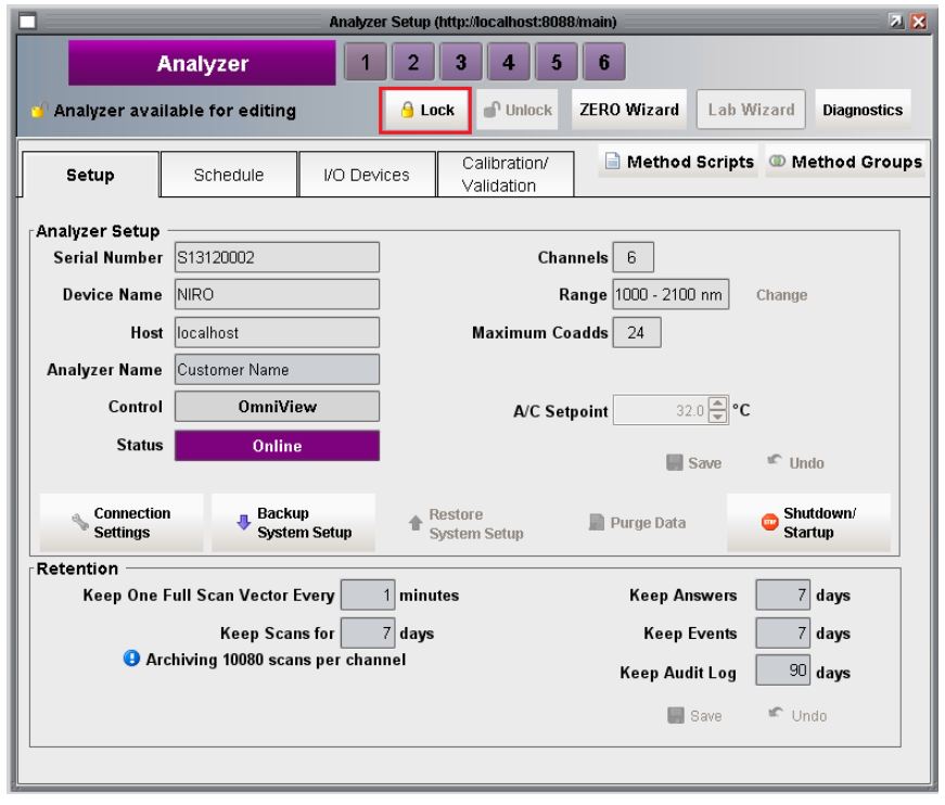
In June 2020, the engineering team completed testing on version 2.5 of the Omniview Process Control Software for the NIR-O Full Spectrum Process Analyzer. In addition to several bug fixes, this version introduces a wizard to help guided users on how to collect data for model creation and validation. The Lab Wizard is accessible from the analyzer setup window and acts as an alternative to Demand Scan functionality that has existed since version 1 of Omniview.

The lab wizard supports two use cases. The first mode is for the collection of data which will be used to create a new NIR calibration. The second mode is for QC operations and enables users to scan a series of samples with an existing NIR calibration. In both modes, the multiple scans can be exported into a single csv file for post-processing or manual submission to a LIMS system.

Overview

The Lab Wizard module was designed to allow users with a NIR-O process analyzer to collect on-demand scans and export them into a single file that is accessible by other software (Unscrambler© software, LIMS systems, etc.). The functionality of the Lab Wizard runs in parallel to the normal process software functionality. Changing channel configuration settings such as the number of scans to average (coadds) will also change the settings for the spectral data collected by the Scheduler. Additionally, the Scheduler can remain active while the Lab Wizard is running. This enables users to collect on demand scans on specific channels with minimal impact to ongoing operations.

Using the Lab Wizard

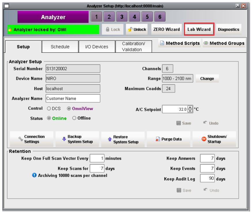
1) To enable the Lab Wizard button, click the Lock button,in the Analyzer window.

2) Click the Lab Wizard button to begin,

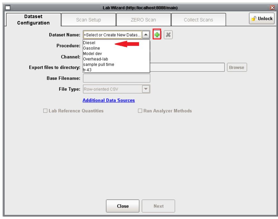
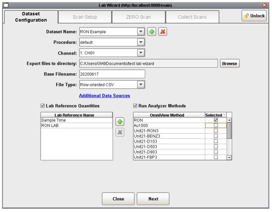
3) The Setup tab of the Lab wizard allows for the general scope or data-set of the on-demand scans to be defined. A user with Technician level privileges can only select a previously defined data-set from the drop down list. A user with Engineer level privileges can select an existing data-set or create a new data-set by clicking the plus button.

4) Once a data-set is selected, click the Next button to proceed to the Scan Setup tab.

Parameters that define a dataset include: file name prefix, file path to export scans to, selecting which channel spectra will be collected on, if any lab reference values will be supplied, if any existing models/methods should be called.  Additionally, lab required meta information such as the time that a sample was pulled can be entered as a lab reference value. The Procedure drop down list is currently a place holder

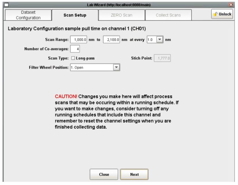
5. The Scan Setup tab allows for modification by a user with Engineer privileges to change the channel configuration.  

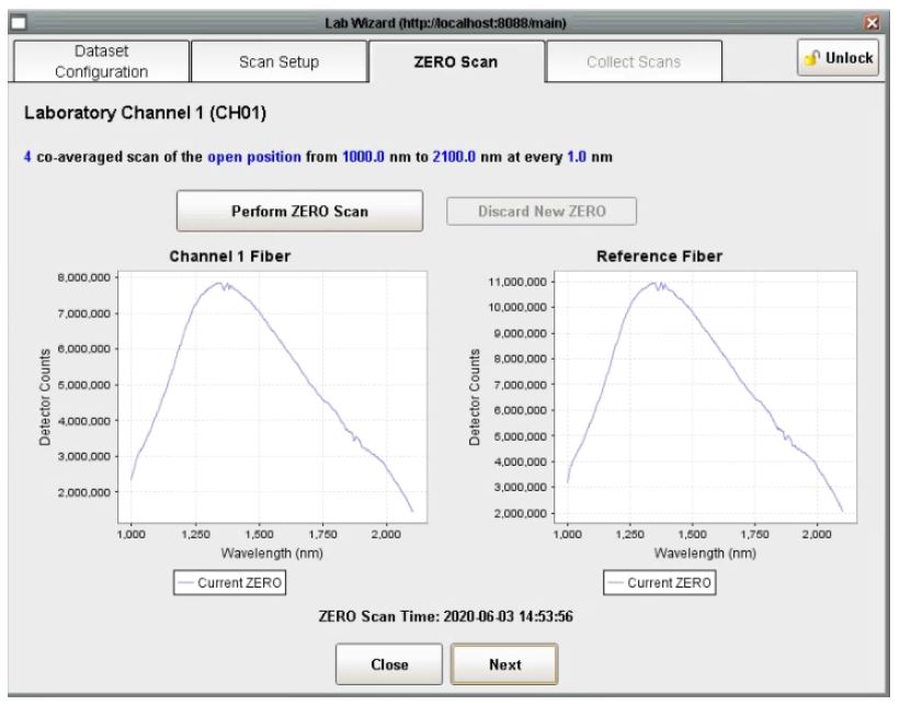
6. The ZERO Scan tab allows for the collection of ZERO scans and follows the same logic as the ZERO Wizard. Both Technician and Engineer users can collect a new zero or proceed with the existing zero scan.

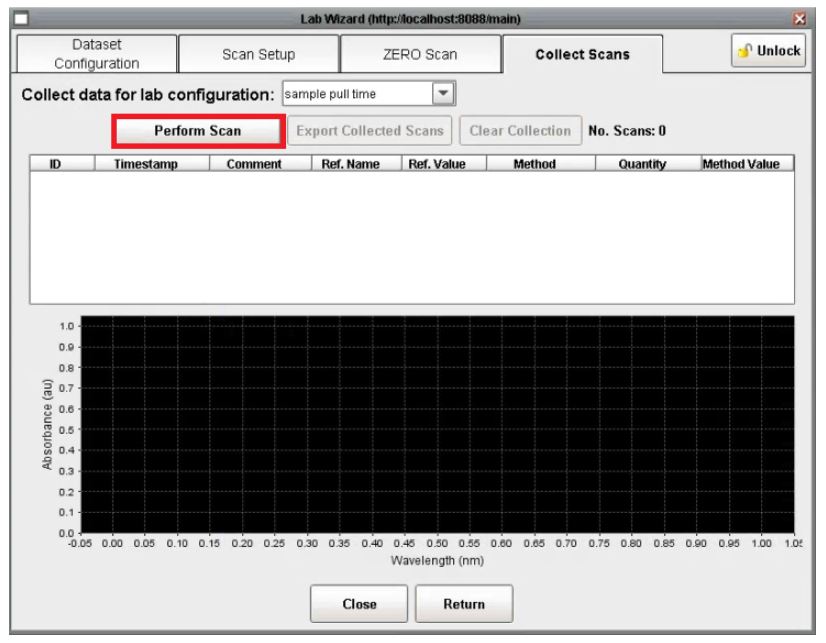
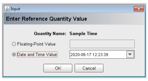
7) The Collect Scans tab allows for data to be collected as defined by the previous tabs. If reference values were setup on the data configuration tab, the user will be prompted for them once the scan is completed. If a sample collection time is to be entered use the date format. Additionally, users will be prompted to provide a comment.  The comment can be a sample name or any other information that may be useful.  Both fields can be left blank. To collect a scan click the Perform Scan Button.

7) The lab reference value or sample scan time can be entered in the popup:

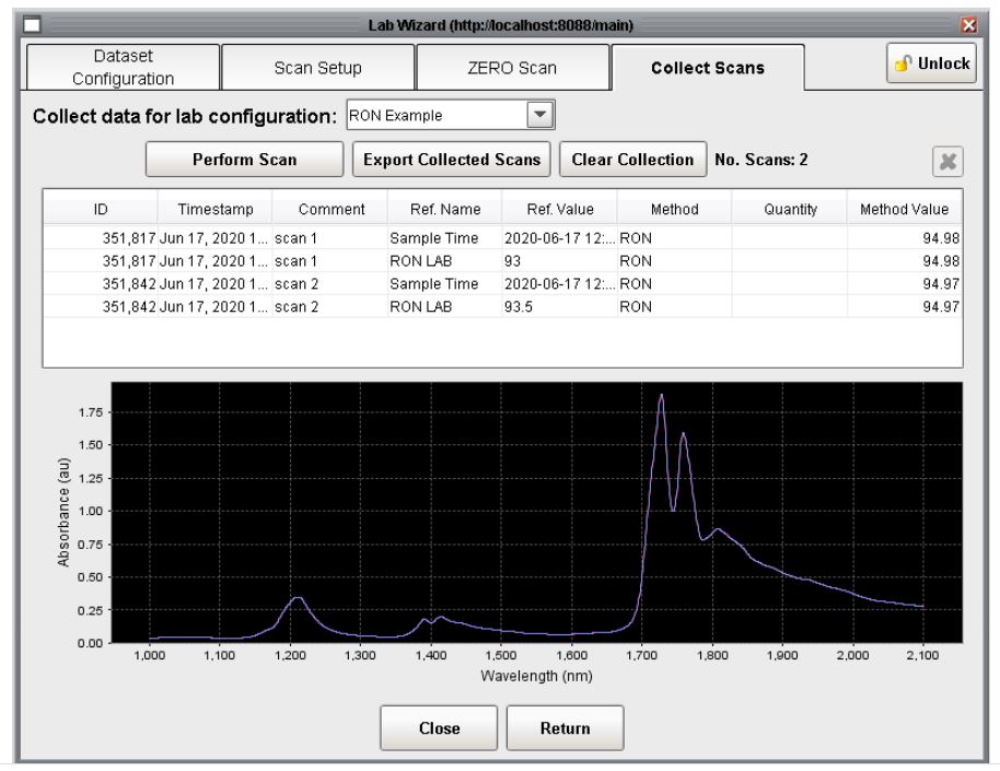
8) Once a scan is complete the spectrum will appear in the chart and tabulated data in the table above it. Additional scans added to the collection will appear in both the table and chart.

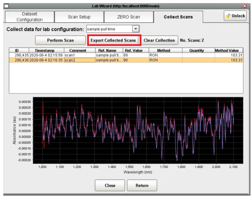
9) To export the collection of scan to a file, click the Export Collected Scans button.  The collection of scans and tabular information will be exported according to the previously selected file format (csv, gwj, etc)

10) Selecting scans in the table enables the deletion button. Scans removed from a collection are still stored in the database. Removing a scan simply removes it from the collection.  The entire collection can be deleted using the Clear Collection button.

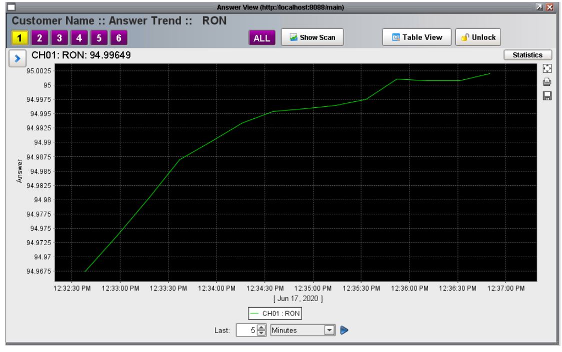
11) A trend chart of Lab Wizard answers can be displayed by opening the Answer window and selecting the data from the list of available answers. At this time, lab reference values cannot be displayed inside of the OmniView process software. To generate a ‘Predicted vs Actual value chart, use the exported file of the collection.

For more information on how to use OmniView software see our YouTube Channel.

Questions? We’re here to help?

Contact Us

Continue reading